Sunday, January 11, 2009

Great Work so far

Great job so far.

I don't think that forgetting to set the pin to an output is causing the problem (I think the atmega turns the pin into an output when it is written to for the first time.)  However, this is the first thing to check!  

I think it turns out the rate of helium leakage is not that bad.  It plumped up just fine as it warmed up and was still at neutral bouyancy on Saturday.  

I will bring in some Vex RC gear for next friday.  

Here is an overview of how the motors are being driven.   


Pin 2

Pin 3


LOW

LOW

Shutdown

LOW

HIGH

On Full Forward

HIGH

LOW

On Full Backward

HIGH

HIGH

Assume off?


Now if we want to control the speed of the motor, we need to turn the level on an off very quickly.  This is called pulse width modulation.  Basically, a DC signal would be ON all the time.  A 50/50 signal would be on half the time and off half the time.  By varying the % time that the pulse is on we can vary the speed of the motor. (basically giving the motor little pulses of power.)

To moderate the speed of the motor we will use the following:

Pin 2

Pin 3


LOW

LOW

Shutdown

LOW

Analog Level

Forward at % ~to level

HIGH

Analog Level

Forward at % ~to 100% - level


Read the following page on doing analog write on the arduino:

For completeness you should probably also look at these pages:

Change the code so that it uses the analogWrite to drive the motor.
Write a bit of code to ramp the motor from 0 up to 100% over 10 seconds and then ramp it down over 10 seconds.  Look at:

Read through the motor code in the blimpduino source after you do all this and make sure you understand what they are doing.

I am torn about the RC code.  I read through it and they are using two seperate inputs.  They are doing all the right decoding for our transmitter gear, but they are setup for standard RC gear.  Ok, I just bought some RC gear.  It should be here by friday.  

Let me know when you get the motors working and I will set you to work on the servo.

Friday, January 9, 2009

Day One!

As Professor Mason would say "Hot diggity! Physics works!" Not that we didn't have any faith in physics, but it's nice when we get things to work. Like our blimp! First, how the day played out, then some pictures, and then what we need to figure out. There will eventually be video, however, I need to do some video editing before I can upload it.

Setting up the blimp took about an hour on its own. Helium had to be put in; unfortunately I put a little too much helium in and the blimp took off even with the board attached (which was about 80 grams) We added about another 15 grams to the back of the blimp and 10 to the front of the blimp, which balanced it out nicely.


We were able to attach the thrusters and chips to the middle of the blimp using a combination of styrofoam and Velcro. The styrofoam was used to put some space between the blimp and the rotor for the vector thruster
s

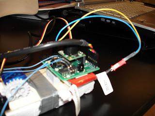


So, after plugging everything in, did it work? Well, we didn't have an RC receiver handy, so we booted it up in autonomous mode. Short answer is yes! it works great! Long answer: it works, but it got itself stuck in a corner and couldn't get out.

Allow me to explain. Upon booting it up, it did exactly as programmed. With the IR beacon off, it hovered about 4 feet off the ground, give or take. There was some slight drifting, but with the air conditioning on it was expected. We then placed the blimp about 8 feet away near the ceiling and activated the IR beacon about waist high on a table. The blimp servos went into self check and then proceeded forward...to the left, away from the receiver. When it was perpendicular to the receiver, it turned right, and head towards the beacon, but also towards the ceiling. It passed over the beacon and tried to turn itself around, and then got stuck in a corner.

After we did the test of the pre-installed BlimpDuino software, we tried to put in our own code. We hooked it up to my laptop and started the IDE and got a bunch of garbage on the serial monitor. We had hooked it up backwards...go figure. We first attempted to make the right motor spin and then turn off. Our code looked something like this

int rightmotor1 = 2;
int rightmotor2 = 3;
int leftmotor1 = 4;
int leftmotor2 = 5;

void setup() // run once, when the sketch starts
{
pinMode(rightmotor1, OUTPUT); // sets the digital pin as output
pinMode(rightmotor2, OUTPUT); // sets the digital pin as output
pinMode(rightmotor1, OUTPUT); // sets the digital pin as output
pinMode(rightmotor2, OUTPUT); // sets the digital pin as output
digitalWrite(rightmotor1, LOW); // Turns right motor off
digitalWrite(rightmotor2, LOW); // Turns right motor off
digitalWrite(leftmotor1, LOW); // turns left motor off
digitalWrite(leftmotor2, LOW); // turns left motor off
}

void loop() // run over and over again
{
digitalWrite(rightmotor1, HIGH); // sets the right motor on high speed
delay(1000); // waits for a second
digitalWrite(righttmotor1, LOW); // sets the right motor off
delay(100);//delays for 1/10 of a second
digitalWrite(righttmotor2,HIGH);//turns the right motor on but in the opposite direction
delay(1000); // waits for a second
digitalWrite(rightmotor1, LOW); // sets the right motor off
digitalWrite(rightmotor2, LOW); // sets the right motor off
digitalWrite(leftmotor1, LOW); // sets the left motor off
digitalWrite(leftmotor2, LOW); // sets the left motor off
delay(1000);
}

The code worked perfectly fine. At this point, to conserve the battery, we hooked it up to a 5v power regulator that was plugged in to the socket. The fans spun, but not very strongly. Then, we modified the code a little bit to alternate between the two.

int rightmotor1 = 2;
int rightmotor2 = 3;
int leftmotor1 = 4;
int leftmotor2 = 5;

void setup() // run once, when the sketch starts
{
pinMode(rightmotor1, OUTPUT); // sets the digital pin as output
pinMode(rightmotor2, OUTPUT); // sets the digital pin as output
pinMode(rightmotor1, OUTPUT); // sets the digital pin as output
pinMode(rightmotor2, OUTPUT); // sets the digital pin as output
digitalWrite(rightmotor1, LOW); // Turns right motor off
digitalWrite(rightmotor2, LOW); // Turns right motor off
digitalWrite(leftmotor1, LOW); // turns left motor off
digitalWrite(leftmotor2, LOW); // turns left motor off
}

void loop() // run over and over again
{
digitalWrite(rightmotor1, HIGH); // sets the right motor on high speed
delay(1000); // waits for a second
digitalWrite(rightmotor1, LOW); // sets the right motor off
delay(100);//delays for 1/10 of a second
digitalWrite(leftmotor1,HIGH);//turns the left motor on
delay(1000); // waits for a second
digitalWrite(rightmotor1, LOW); // sets the right motor off
digitalWrite(rightmotor2, LOW); // sets the right motor off
digitalWrite(leftmotor1, LOW); // sets the left motor off
digitalWrite(leftmotor2, LOW); // sets the left motor off
delay(1000);
}

Right motor turns on, and then silence. And more silence. then right motor turns on, and then silence. The left motor wasn't working for some reason. We noticed that the fans were spinning a little slow, so we thought maybe there wasn't enough current to power the board. So we switched out the 5v for a 12v and tried it again. Same results. We uploaded the original code to test it and it worked just fine. Vector servos fired off, then each of the fans tested themselves. So at this point, we've been pondering it until about 1730 and we called it a day.

So, things to think about until our next meeting.
- What is causing the right motor to spin correctly, but not the left?
- RC receiver: how to build and build
- I noticed that the blimp likes to bump into the ceiling a lot during autonomous mode. I know that the US sensor can detect how far from the ground it is, but is the blimp programmed to know how much top clearance it has?
- Other forms of navigation (I'm personally thinking visual recognition, but we'll see how far along in coding we get)

Notes
- The helium seems to leak at a rate much faster than a week. In about four hours the blimp went from stretch taut to a little squishy.
- Prof Mason, if you didn't get my email, I think I did not upload the autonomous software back in before I left for the day. Right now I think it will make right turns only. =\

**Edit: I just noticed as I was inspecting our code, we never specified pinmode(leftmotor1,output) in the void setup section. It reads as right and right for each. I wonder if that has something to do with it.....**

Thursday, January 8, 2009

More research

1. Arduino Pro plugged in (image from Arduino)


2. Please note that the boards operates at 3.3V (unlike most other Arduino boards, which use 5V); be careful when connecting external components. (Quoted from Arduino yet again). From details about the board, I don't see anything that says we can use a 5v (link)

3. Looking at some sample code I think it runs using PWM. This was just a test run of the blimp. I'll check the actual code once I load everything onto my laptop tonight.


Oh, and searching around the internet I found another 52" blimp that says it only takes 5 cubic feet of helium to make it go. I'll check with Air Gas and Praxair tomorrow, as well as Party City.

Question Update

1. Look up the interface to program the arduino on board(In the blimp duino docs). 
- We can use the Arduino Pro IDE to upload new code. The code is available for free at Arduino. 
OK Install this on your laptop.  What I meant was the physical pinout.  The USB-TTL cable has a 6 pin header on it.  I assume this just plugs into the board.  Find a picture of how it plugs in and post it. 

2. Does the Arduino need need a ttl interface or is the inverter already board? 
This can be an FTDI TTL-232R-3V3 USB - TTL Level Serial Converter Cable, the SparkFun FTDI Basic Breakout Board, or any other USB to 3.3V TTL serial convertor.   I have a FTDI TTL - 232R 5V USB cable.  See if you can find out if the arduino on the board is 5V tolerant (I suspect that it is, but I would hate to burn it out!) 

4. What does the program loaded on the Arduino by default do? 
- The board comes preassembled and preprogrammed with two modes: 
a. RC Mode 
- The chip will auto detect an RC signal. After it’s been recognized, the RC controls will adjust the vectoring thrusters and spin speed for thrust, pitch, and lift. 
OK, we will have to look at this.  Typically RC controllers output a pulse between 1ms and 2ms long.  A value of 1.5 ms corresponds to dead stick (0).  1 would be maximum negative and 2 would be maximum positive.  The RC gear that I have(vex) combines all the channels into one.  Look at this reference: 
also look up PPM encoding vs. PCM encoding.  See if you can find out which one the blimpduino uses. 

6. What is the RC protocol that is used? 
- Not too sure what this means. I read though the blog posts on DIY and found that it runs on dual channel, one for thrust one for steering. We turn on the RC controller first, then activate the blimp. The blimp is preprogrammed to auto detect the RC.  Again see the above PPM vs. PCM question.

8. How to mount all of this stuff on the blimp? (Look at the instructions) 
I will bring a bunch of velco. 

Back to the Helium Question:
(626) 338-4712
(909) 629-5031

Find out if they will fill our empty Argon/Hydrogen (99/1)  Gas tank with helium.  Failing that see if they will fill our empty nitrogen gas tank with Helium.  I belive these are 9 cubic meter tanks.  Find out prices and other options.

Blimp pre research

These are the responses to the questions posted by Prof Mason. I'll be installing the IDE software on my laptop tonight so I can bring it tomorrow...hopefully it does not over heat like it normally does. I noticed that there is a USB to TTL cable, so hopefully we have one of those. Other wise we'll need a computer that has a serial port.

1. Look up the interface to program the arduino on board(In the blimp duino docs).
- We can use the Arduino Pro IDE to upload new code. The code is available for free at Arduino.

2. Does the Arduino need need a ttl interface or is the inverter already board?
- The board comes without built-in USB circuitry, so an off-board USB-to-TTL serial convertor must be used to upload new code. This can be an FTDI TTL-232R-3V3 USB - TTL Level Serial Converter Cable, the SparkFun FTDI Basic Breakout Board, or any other USB to 3.3V TTL serial convertor.

3. How to mount the ultrasonic sensor on the board?
- It plugs in. Here is a picture of the orientation of the US sensor.

4. What does the program loaded on the Arduino by default do?
- The board comes preassembled and preprogrammed with two modes:
a. RC Mode
- The chip will auto detect an RC signal. After it’s been recognized, the RC controls will adjust the vectoring thrusters and spin speed for thrust, pitch, and lift.
b. Autonomous mode
- Putting it in this mode will have the blimp find it’s bearings and hover over the ground. Once the IR beacon has been activated and detected, it will try to move towards the beacon, adjusting lift to match the beacons height. If the signal is lost, it will go into standby and hover.

5. Find a link to the source for the program and post it here.
- Source code link ( you have to download and unzip it)

6. What is the RC protocol that is used?
- Not too sure what this means. I read though the blog posts on DIY and found that it runs on dual channel, one for thrust one for steering. We turn on the RC controller first, then activate the blimp. The blimp is preprogrammed to auto detect the RC.

7. Is it supported by the board?
- The RC mode works in tandem with autonomous. We can control the blimp via RC, and once we let go, the Arduino processor will kick in and operate.

8. How to mount all of this stuff on the blimp? (Look at the instructions)
- Tape. Lots of tape. For testing, we can just use regular tape/packaging tape to hold it up. To make it more permanent, we can Velcro the base of the board to the bottom of the blimp. When we fill the blimp with helium, we need to fill it about ¾, then attach the boards and continue to fill or add weights until it can support itself in midair. The blimp leaks over the course of a week, so we’ll need lots helium to refill ever week.


One more day!

Wednesday, January 7, 2009

Yay it's here!

We got it today! Yay! Professor Mason had posted some questions earlier regarding the programming and assembly, I'll get to those tomorrow. Until then, bask in the glory!


The blimp itself! It's a monster 52" blimp. We better start hunting for that helium....


Here's the Ultrasonic Sensor from the top. Model is Maxbotic EZ1.


A profile shot of the Ultrasound. The black rectangular part at the bottom connects directly to the main board.


Here it is!! The brains behind the blimp. At the top are the Vectoring Differential thrusters. Lego blogs and rotar in blue. Main board at the bottom in green. The batter is a 7.4 V LiPo battery. Did some reading...stores 2100 J of energy and has a 99.8% discharge efficieny. Frying is not a good thing =\


Closer shot of the front


Close of up one of the thrusters.

The parts are here!

The blimpduino parts arrived today.

There is a assembled board with the servo driven vectored differential thurst module. There is a balloon envelope with foam fins. A pololu IRB02A IR beacon. A max sonar EZ1.

To do:
  • Look up the interface to program the arduino on board(In the blimp duino docs)
  • Does the arduino need need a ttl interface or is the inverter already board?
  • How to mount the ultrasonic sensor on the board?
  • What does the program loaded on the arduino by default do?
  • Find a link to the source for the program and post it here.
  • What is the RC protocol that is used?
  • Is it supported by the board?
  • How to mount all of this stuff on the blimp? (Look at the instructions)
The RC gear we are using encodes all of the channels on a single line (easy for microprocessors)