The first thing we attempted to do today was mount a wireless digital camera to the blimp to see if the blimp could lift both camera and the motor board. Result: crashing nose first into the ground. The motor board itself is roughly 80 grams, but the digital camera is roughly another 80 grams. Even after attempting to push all the air out with a straw and refilling with helium, there was not enough lift to carry camera and board. We also took apart the camera and attached only the camera with it's board, but it still was too much weight. Our next step is to get rid of the Li-Ion battery on the camera and connect the camera to the LiPo battery on the motor.
Next came the RC. We test the settings for almost an hour until we figured out what would work best. While DIY said to plug the servo plug into throttle, we plugged it into elevation instead. We then plugged RC1 and RC2 into throttle and rudder. With our RC controller, the left stick controlled the throttle forward and reverse, while up and down on the right stick controlled the angle of the servo for the up and down, while left and right turned the fans on the right and left side respectively. There were some issues though. The throttle control was a little off: reverse was much stronger then forward. Basically, neutral was still going in reverse, and all the way forward was barely going forward. We'll probably have to go into the RC control to modify that, which I'll poke into this weekend. Also, rudder control was a little ungainly. I think that another one of the plugs will allow better turning; ideally, to turn left, right motor spins forward while left motor spins backwards. This will allow for much tighter turner. That'll be for Tuesday.
Ultrasound came next. While in the previous video (see about three posts prior) I was able to make the fan spin high or low depending on the length of the signal that came back, it would only spin low for small distances and high for large distances. So, I did the following:
//ultrasound mark 2
int usi = 16;
int uso = 15;
int rm1 = 2;
int rm2 = 3;
int lm2 = 5;
int lm1 = 4;
void setup()
{
Serial.begin(19200);
pinMode(usi, INPUT);
pinMode(uso, OUTPUT);
pinMode(rm1, OUTPUT);
pinMode(rm2, OUTPUT);
pinMode(lm2, OUTPUT);
pinMode(lm1, OUTPUT);
}
void loop()
{
int length = 0;
digitalWrite(uso, HIGH);
delay(40);
length=pulseIn(usi, HIGH, 200000);
digitalWrite(uso, LOW);
length=(length/147); //pulse width is 147us/inch so length is in inches
Serial.println(length);
if(length>=40 && length<=45)
{
analogWrite(rm2, 0);
analogWrite(lm2, 0);
}
if(length>45)
{
analogWrite(rm2, length);
analogWrite(lm2, length);
}
if(length<40)
{
analogWrite(rm2, 45-length);
analogWrite(lm2, 45-length);
}
}
This made it so that a distance of 40-45 inches from the ground was the idea hovering distance. Anything below that, the fan would spin at 40-d, where d is the distance from the ground, so the farther from the ground it got the slower it would spin and visa versa. Another thing that we confirmed was that the board ran using the digital pins TX and RX. This means we have to use two separate lines of code to send out a pulse and read the pulse (the 147 means 147 us/inch). The ultrasound also supports another pin, which is analog. This way, we would be able to have it do analogread to measure the distance of the waves; however, we're not sure if the board has a pin programmed for the analog on the ultrasonic.
Next we worked on the IR receiver and this was a bugger of an problem to figure out. I started with a code like this.
int IR_front = 8;
int IR_back = 7;
int IR_right = 6;
int IR_left = 9;
int ledn = 12;
int lede = 17;
int leds = 11;
int ledw = 13;
int vf = 0;
int vb = 0;
int vl = 0;
int vr = 0;
void setup()
{
Serial.begin(57600);
pinMode(ledn, OUTPUT);
pinMode(lede, OUTPUT);
pinMode(leds, OUTPUT);
pinMode(ledw, OUTPUT);
pinMode(IR_front, INPUT);
pinMode(IR_back, INPUT);
pinMode(IR_left, INPUT);
pinMode(IR_right, INPUT);
digitalWrite(ledn, LOW);
digitalWrite(leds, LOW);
digitalWrite(lede, LOW);
digitalWrite(ledw, LOW);
}
void led_off()
{
digitalWrite(ledn, LOW);
digitalWrite(leds, LOW);
digitalWrite(lede, LOW);
digitalWrite(ledw, LOW);
}
void loop()
{
vf = digitalRead(IR_front);
vb = digitalRead(IR_back);
vl = digitalRead(IR_left);
vr = digitalRead(IR_right);
Serial.print(vf);
Serial.print(',');
Serial.print(vb);
Serial.print(',');
Serial.print(vl);
Serial.print(',');
Serial.println(vf);
digitalWrite(ledn, HIGH);
digitalWrite(leds, HIGH);
diitalWrite(ledw, HIGH);
digitalWrite(lede, HIGH);
delay(10);
led_off();
}
When we ran the code, all the lights on the board turned on! It was weird. We then tried pushing a bunch of infrared remotes and nothing worked. Same with the IR beacon that came with the setup. The serial prints were just giving us 1's with an occasional 0. Then we turned off the beacon and the lights remained on. We turned them back on and that's when Prof Mason noticed the flickering. We turned off the beacon and the flickering stopped. Hmmmmm....perhaps it's backwards...instead of trigger High, like we thought, maybe the beacon made the IR trigger a low spot and that's what makes it detect it. To test it, we hooked up a spectrometer and turned off all infrared in the area....and we got two bars! The IR receivers were programmed on high! So we modified the code
int IR_front = 8;
int IR_back = 7;
int IR_right = 6;
int IR_left = 9;
int ledn = 12;
int lede = 17;
int leds = 11;
int ledw = 13;
int vf = 0;
int vb = 0;
int vl = 0;
int vr = 0;
void setup()
{
Serial.begin(57600);
pinMode(ledn, OUTPUT);
pinMode(lede, OUTPUT);
pinMode(leds, OUTPUT);
pinMode(ledw, OUTPUT);
pinMode(IR_front, INPUT);
pinMode(IR_back, INPUT);
pinMode(IR_left, INPUT);
pinMode(IR_right, INPUT);
digitalWrite(ledn, LOW);
digitalWrite(leds, LOW);
digitalWrite(lede, LOW);
digitalWrite(ledw, LOW);
}
void led_off()
{
digitalWrite(ledn, LOW);
digitalWrite(leds, LOW);
digitalWrite(lede, LOW);
digitalWrite(ledw, LOW);
}
void loop()
{
vf = digitalRead(IR_front);
vb = digitalRead(IR_back);
vl = digitalRead(IR_left);
vr = digitalRead(IR_right);
Serial.print(vf);
Serial.print(',');
Serial.print(vb);
Serial.print(',');
Serial.print(vl);
Serial.print(',');
Serial.println(vf);
if(vf==LOW)
{
digitalWrite(ledn, HIGH);
}
if(vb==LOW)
{
digitalWrite(leds, HIGH);
}
if(vl==LOW)
{
digitalWrite(ledw, HIGH);
}
if(vr==LOW)
{
digitalWrite(lede, HIGH);
}
delay(10);
led_off();
}
And Bam! Success! Another thing we did was put the beacon farther away, and that caused only one LED to light up. With the beacon too close, there was too much reflection and it caused all the LED's to light up.
So, things to work on.
1. Modify RC code for the throttle.
2. Get a small plug and wires for the battery
3. Get Robo Realm and the wireless camera to sync with my laptop.
That's everything I can remember. Anything to add Professor?
Friday, January 16, 2009

IR Beacon
Great progress today. I will look forward to your writeup. I looked at the beacon on my scope. Sorry about the poor quality of the pictures. I think that the beacon is just sending "001001001" etc. Here is what I see on the screen. There is a carrier signal with a period of about 18 us. This corresponds to a frequency of about 56 Khz(Which makes sense since this is a 56khz beacon.) On top of that I see two short pulses followed by one long. 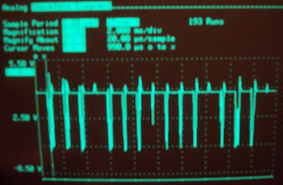

There appears to be a lot of noise in this image due to aliasing with the carrier. Below is a zoom in on the pulses. The smaller pulse has a pulse width of about 1.4ms and the longer pulse has a width of 2.4ms. Looking at the vishay datasheet:
I have usually use the sony protocol which uses a different set of pulse widths. (1.2 ms for 0 and 1.8 ms for 1.) Take a look at this page for an explanation:
PS:
Here is a nice overview of how IR remotes work:
http://www.sbprojects.com/knowledge/ir/ir.htm
Ok, I think I found what the pololu beacon is using. It appears that the pololu beacon is using what looks like the RCA protocol! Here is a link to the description:
http://www.sbprojects.com/knowledge/ir/rca.htm
I have a couple of universal remotes that will produce this protocol, so with any luck it should be pretty straightforward to drive the blimp with the IR remote! (A worthy project I think) This would require no additional hardware or weight on the balloon.
http://www.sbprojects.com/knowledge/ir/ir.htm
Ok, I think I found what the pololu beacon is using. It appears that the pololu beacon is using what looks like the RCA protocol! Here is a link to the description:
http://www.sbprojects.com/knowledge/ir/rca.htm
I have a couple of universal remotes that will produce this protocol, so with any luck it should be pretty straightforward to drive the blimp with the IR remote! (A worthy project I think) This would require no additional hardware or weight on the balloon.
Thursday, January 15, 2009
Update
I tested the board with the 2 amp cord and motor works fine now. I was also able to plug in the transmitter to the board using some cables and got the thruster control to work; however, the battery died before I could adjust the aileron controls.
1.
2. right motor back
3. right motor forward
4. left motor back
5. left motor forward
6. IR right
7. IR back
8. IR front
9. IR left
10. Servos
11 LED S
12. LED N
13. LED W
14
15. Ultrasonic out
16. Ultrasonic in
17. LED E
This is a list of pins and the things that they control. The numbers on the IR receiver are 19 711 v34156.
Alright, now for some fun stuff.
I was able to program the LED's to blink:
and here is a video of the ultrasound and motor combination. Note: the code for the ultrasound is a redone version of the original code, i just played with the names and things like that. I was not able to get it to do analog read....yet
Still working on the IR system at the moment...
1.
2. right motor back
3. right motor forward
4. left motor back
5. left motor forward
6. IR right
7. IR back
8. IR front
9. IR left
10. Servos
11 LED S
12. LED N
13. LED W
14
15. Ultrasonic out
16. Ultrasonic in
17. LED E
This is a list of pins and the things that they control. The numbers on the IR receiver are 19 711 v34156.
Alright, now for some fun stuff.
I was able to program the LED's to blink:
and here is a video of the ultrasound and motor combination. Note: the code for the ultrasound is a redone version of the original code, i just played with the names and things like that. I was not able to get it to do analog read....yet
Still working on the IR system at the moment...
Wednesday, January 14, 2009
Multiple Beacons
When you have finished everything in the previous post, take a look at this.
http://diydrones.com/profiles/blogs/705844:BlogPost:39610
It looks like they haven't solved this problem either. If you can read the part numbers off the IR receivers, I can do a bit of research. I am afraid that they used 56 Khz units on the board.
http://diydrones.com/profiles/blogs/705844:BlogPost:39610
It looks like they haven't solved this problem either. If you can read the part numbers off the IR receivers, I can do a bit of research. I am afraid that they used 56 Khz units on the board.
Motor stalling and more
My first thought is that the power supply we are using can't source enough current for both motors. (I take it you are not running off the battery?)
What you are describing sounds like the voltage to the micro is getting to low, which causes it to reset.
Get a power supply that is already soldered to a pair of 0.1 inch pins from Ben. Try to find one that will source at least 1 Amp. The little guy I had left there will only provide 0.5 Amps.
I just soldered up a 2 Amp 5.5 Volt supply. This should work.
I received a set of standard RC gear today. The only thing we need to look at is making a plug to power the RC receiver. I need to know if the board has an output to power the RC receiver and if so, what kind of pins does it have so I can make an adapter.
I also dug out a mini camera. It needs about 8 volts to run, so it should work off of the RC battery as long as it is fresh.
Things to work on:
http://www.maxbotix.com/MaxSonar-EZ1__FAQ.html
Add to your motor code a bit of code that will read the Sonar Sensor. Set the speed of one of the motors equal to the value of the sonar sensor. (So when the sensor is reading far away the motor will be on high. As the object gets closer the motor will go slower. Now reverse it so that that motor runs high when an object is close and slow when an object is far.
http://www.arduino.cc/en/Reference/DigitalRead
Skim this:
http://www.vishay.com/docs/81733/tsop382.pdf
http://profmason.com/?p=627
Here is a bit about the beacons:
http://www.robotshop.us/pololu-ir-beacon-development-kit-1.html
There is a detailed description at:
http://ww1.microchip.com/downloads/en/AppNotes/00657.pdf
What you are describing sounds like the voltage to the micro is getting to low, which causes it to reset.
Get a power supply that is already soldered to a pair of 0.1 inch pins from Ben. Try to find one that will source at least 1 Amp. The little guy I had left there will only provide 0.5 Amps.
I just soldered up a 2 Amp 5.5 Volt supply. This should work.
I received a set of standard RC gear today. The only thing we need to look at is making a plug to power the RC receiver. I need to know if the board has an output to power the RC receiver and if so, what kind of pins does it have so I can make an adapter.
I also dug out a mini camera. It needs about 8 volts to run, so it should work off of the RC battery as long as it is fresh.
Things to work on:
- How is the ultrasound being read? What channel is it on? Read this: http://www.arduino.cc/en/Reference/AnalogRead
http://www.maxbotix.com/MaxSonar-EZ1__FAQ.html
Add to your motor code a bit of code that will read the Sonar Sensor. Set the speed of one of the motors equal to the value of the sonar sensor. (So when the sensor is reading far away the motor will be on high. As the object gets closer the motor will go slower. Now reverse it so that that motor runs high when an object is close and slow when an object is far.
- There are 4 NSEW directional LEDs on the board. Figure out what channels they are on. Write a program that turns them on and off sequentially.
- How are the IR sensors being read? What channel are they on?
http://www.arduino.cc/en/Reference/DigitalRead
Skim this:
http://www.vishay.com/docs/81733/tsop382.pdf
- You should be able to read a series of 1s and 0s from each of the IR sensors using the IR beacon as a source. Write a bit of code that reads each IR sensor and then sets the corresponding LED on if it is receiving infrared light.
- If you have time, try to figure out some code to decode a signal from one of the IR sensors. The signal is a set of pulses that repeats about every 20ms and starts with the channel being held low for about 4ms or so. I don't know if the IR beacon is transmitting just straight on off or something more interesting. You can use any standard TV or VCR remote for testing. I will bring in a sony standard remote on Friday.
http://profmason.com/?p=627
Here is a bit about the beacons:
http://www.robotshop.us/pololu-ir-beacon-development-kit-1.html
There is a detailed description at:
http://ww1.microchip.com/downloads/en/AppNotes/00657.pdf
Monday, January 12, 2009
Motor Update and Videos
So I managed to get both motors to work! Turns out with the digital write, the setup did matter, and we had to specify the left and right motors. However, with the analog setup, we did not have to specify; for the Arduino Pro/Blimpduino board, port 3 and 5 are pre-programmed as analog. Anyways, here's the code for an analog program I had the motor do. It amps up the motor over 10 seconds from 0 to full, holds for half a second, then cranks it back down to zero and holds again.
int rightmotor1 = 2;
int rightmotor2 = 3;
int leftmotor1 = 5;
int leftmotor2 = 4;
void setup()
{
pinMode(rightmotor1, OUTPUT);
pinMode(leftmotor2, OUTPUT);
digitalWrite(rightmotor1, LOW);
digitalWrite(leftmotor2, LOW);
}
void loop()
{
int i;
int j;
for(i=0; i<=255; i++)
{
analogWrite(rightmotor2, i);
analogWrite(leftmotor1, i);
delay(45);
}
analogWrite(rightmotor2, 255);
analogWrite(leftmotor1, 255);
delay(500);
for(j=255; j>=0; j--)
{
analogWrite(rightmotor2, j);
analogWrite(leftmotor1, j);
delay(45);
}
analogWrite(rightmotor2, 0);
analogWrite(leftmotor1, 0);
delay(2000);
}
I noticed some funny things. After three or four runs going from zero to full to back, the fans would stop following the program. I could audibly here it click and restart from the beginning. I turned the chip off, waited a minute, then restarted. It ran the program once, got almost through the second run and then clicked off and reset itself. I'm thinking possible over heating? Not too sure. I don't think we'll be able to run it at full blast all the time. Also, I noticed thats the motor starts, it stalls and does not move even though I can hear the motor whining. I am thinking that there is initial static friction that causes it not to open, or the current is too weak to trip the motor.
Videos will be uploaded momentarily
int rightmotor1 = 2;
int rightmotor2 = 3;
int leftmotor1 = 5;
int leftmotor2 = 4;
void setup()
{
pinMode(rightmotor1, OUTPUT);
pinMode(leftmotor2, OUTPUT);
digitalWrite(rightmotor1, LOW);
digitalWrite(leftmotor2, LOW);
}
void loop()
{
int i;
int j;
for(i=0; i<=255; i++)
{
analogWrite(rightmotor2, i);
analogWrite(leftmotor1, i);
delay(45);
}
analogWrite(rightmotor2, 255);
analogWrite(leftmotor1, 255);
delay(500);
for(j=255; j>=0; j--)
{
analogWrite(rightmotor2, j);
analogWrite(leftmotor1, j);
delay(45);
}
analogWrite(rightmotor2, 0);
analogWrite(leftmotor1, 0);
delay(2000);
}
I noticed some funny things. After three or four runs going from zero to full to back, the fans would stop following the program. I could audibly here it click and restart from the beginning. I turned the chip off, waited a minute, then restarted. It ran the program once, got almost through the second run and then clicked off and reset itself. I'm thinking possible over heating? Not too sure. I don't think we'll be able to run it at full blast all the time. Also, I noticed thats the motor starts, it stalls and does not move even though I can hear the motor whining. I am thinking that there is initial static friction that causes it not to open, or the current is too weak to trip the motor.
Videos will be uploaded momentarily
Subscribe to:
Posts (Atom)