I measured the motor and the RC transmitter combined, and that came out to 108.1 grams. With the blimp envelope, that comes out to roughly 123 grams.
The length of the blimp is 52". For a diameter, I got approximately 26". The rough volume of the blimp is 10.35 cu. ft. Using pVg, I got a total upward lift of .81 N. The mass allowed for this lift is 83 grams, which is just enough to lift the motor by itself (motor is 79 g).
The 36" balloon would give us an upward lift of 1.55 N, so the new payload would be 159 grams. I did some reading and the 52" x 36"/37" is for higher altitudes. The air is less dense up there, so the mylar balloon will actually hold 2 cubic feet more. This size balloon can hold a maximum of 20 cubic feet of helium. This balloon would be much better at lifting heavier payloads, but we would need a lot more helium. Also, for the amount of lift it gives (about 30 more grams) I don't know if it would be worth it.
The batteries just ran out on the blimp; I'll need our ghetto charger to get it recharged =P
By the way, I still don't quite understand servo controls.
Tuesday, January 20, 2009

Monday, January 19, 2009
New things to do...
We need more payload.
Do some calculations.
What is the current payload of the envelope when it is full?
What is the volume of the envelope? Make appropriate approximations. The website says "5 cubic feet" does this match what you measure?
What is the diameter of the envelope?
If the envelope is filled with 90% pure helium and helium has a density of .18 kg/m3. Air has a density of 1.2 kg/m3. Given the volume of the envelope, what should the theoretical payload be?
The mass of the envelope is about 15 grams. Is our measured payload even close?
I can get a 52" x 36" envelope here in about a week or so. I only want to if it will solve our problems.
On other topics:
Write some code to read the ultrasonic sensor and then have the blimp hover exactly 1 meter above the ground. You know how to read the US and control the motors and you have already tied them together. Now you need to tie them together in a meaningful way so that feedback from the us is controlling the blimps altitude.
The most common scheme for doing this is called PID (proportional integral derivative) control. This sounds fancy, but it is pretty simple. For our purposes I don't think we will need the integral portion of it, since the balloon will oscillate a LOT.
Read this overview of control systems
Proportional control just means that your output is propotional to the difference between the desired altitute and the current altitude. IE if we are really far from where we want to be, we should spin the motors fast to get there. If we are close, we should spin the motors slowly so that we don't overshoot.
In practice we define and error as
error = desired value - current value.
The proportional part just means that the output to the motors is proportional to the error!
Output = k1 * error Where k1 is some constant which is tuned manually. (When you take a control theory class you will learn lots more about this but for now, just try different numbers until it works.)
Read this section of my friend alex's web page: Proportional Control
The derivative part of proportional derivative control is as follows. We wnat to be traveling parallel to the floor. If the rate of change of the error is large then we are moving toward or away from it and should provide counter thrust to prevent overshoot.
Calculate the rate of change of the error by storing error in a variable and then taking the difference. If we were really worried about things, we would look at the elapsed time for each loop and divide, but that is close enough to constant that it shouldn't matter.
Now read this part on Derivative Control.
We will use the derivative to modify the output as follows:
Output = k1 * error - k2 * DError
The DError term is opposing the error term.
For putting this together see: Proportional Derivative Control
I need to talk to Alex about moving that stuff to a friendlier site.
Ok, let me know how your progress goes. I will try to get in and drop of the IR remote so we can play with that.
Friday, January 16, 2009
Digital Camera Online!
Just got the digi cam to sync with my laptop. Currently reading tutorials on programming and object recognition. I did some reading on the RC code as well. We need to leave the control stick in neutral when the board boots up or else it will memorize a different position as neutral. I think we've been playing with the sticks whenever we boot it up. I'll give it a try Tuesday.
Day Two~
The first thing we attempted to do today was mount a wireless digital camera to the blimp to see if the blimp could lift both camera and the motor board. Result: crashing nose first into the ground. The motor board itself is roughly 80 grams, but the digital camera is roughly another 80 grams. Even after attempting to push all the air out with a straw and refilling with helium, there was not enough lift to carry camera and board. We also took apart the camera and attached only the camera with it's board, but it still was too much weight. Our next step is to get rid of the Li-Ion battery on the camera and connect the camera to the LiPo battery on the motor.
Next came the RC. We test the settings for almost an hour until we figured out what would work best. While DIY said to plug the servo plug into throttle, we plugged it into elevation instead. We then plugged RC1 and RC2 into throttle and rudder. With our RC controller, the left stick controlled the throttle forward and reverse, while up and down on the right stick controlled the angle of the servo for the up and down, while left and right turned the fans on the right and left side respectively. There were some issues though. The throttle control was a little off: reverse was much stronger then forward. Basically, neutral was still going in reverse, and all the way forward was barely going forward. We'll probably have to go into the RC control to modify that, which I'll poke into this weekend. Also, rudder control was a little ungainly. I think that another one of the plugs will allow better turning; ideally, to turn left, right motor spins forward while left motor spins backwards. This will allow for much tighter turner. That'll be for Tuesday.
Ultrasound came next. While in the previous video (see about three posts prior) I was able to make the fan spin high or low depending on the length of the signal that came back, it would only spin low for small distances and high for large distances. So, I did the following:
//ultrasound mark 2
int usi = 16;
int uso = 15;
int rm1 = 2;
int rm2 = 3;
int lm2 = 5;
int lm1 = 4;
void setup()
{
Serial.begin(19200);
pinMode(usi, INPUT);
pinMode(uso, OUTPUT);
pinMode(rm1, OUTPUT);
pinMode(rm2, OUTPUT);
pinMode(lm2, OUTPUT);
pinMode(lm1, OUTPUT);
}
void loop()
{
int length = 0;
digitalWrite(uso, HIGH);
delay(40);
length=pulseIn(usi, HIGH, 200000);
digitalWrite(uso, LOW);
length=(length/147); //pulse width is 147us/inch so length is in inches
Serial.println(length);
if(length>=40 && length<=45)
{
analogWrite(rm2, 0);
analogWrite(lm2, 0);
}
if(length>45)
{
analogWrite(rm2, length);
analogWrite(lm2, length);
}
if(length<40)
{
analogWrite(rm2, 45-length);
analogWrite(lm2, 45-length);
}
}
This made it so that a distance of 40-45 inches from the ground was the idea hovering distance. Anything below that, the fan would spin at 40-d, where d is the distance from the ground, so the farther from the ground it got the slower it would spin and visa versa. Another thing that we confirmed was that the board ran using the digital pins TX and RX. This means we have to use two separate lines of code to send out a pulse and read the pulse (the 147 means 147 us/inch). The ultrasound also supports another pin, which is analog. This way, we would be able to have it do analogread to measure the distance of the waves; however, we're not sure if the board has a pin programmed for the analog on the ultrasonic.
Next we worked on the IR receiver and this was a bugger of an problem to figure out. I started with a code like this.
int IR_front = 8;
int IR_back = 7;
int IR_right = 6;
int IR_left = 9;
int ledn = 12;
int lede = 17;
int leds = 11;
int ledw = 13;
int vf = 0;
int vb = 0;
int vl = 0;
int vr = 0;
void setup()
{
Serial.begin(57600);
pinMode(ledn, OUTPUT);
pinMode(lede, OUTPUT);
pinMode(leds, OUTPUT);
pinMode(ledw, OUTPUT);
pinMode(IR_front, INPUT);
pinMode(IR_back, INPUT);
pinMode(IR_left, INPUT);
pinMode(IR_right, INPUT);
digitalWrite(ledn, LOW);
digitalWrite(leds, LOW);
digitalWrite(lede, LOW);
digitalWrite(ledw, LOW);
}
void led_off()
{
digitalWrite(ledn, LOW);
digitalWrite(leds, LOW);
digitalWrite(lede, LOW);
digitalWrite(ledw, LOW);
}
void loop()
{
vf = digitalRead(IR_front);
vb = digitalRead(IR_back);
vl = digitalRead(IR_left);
vr = digitalRead(IR_right);
Serial.print(vf);
Serial.print(',');
Serial.print(vb);
Serial.print(',');
Serial.print(vl);
Serial.print(',');
Serial.println(vf);
digitalWrite(ledn, HIGH);
digitalWrite(leds, HIGH);
diitalWrite(ledw, HIGH);
digitalWrite(lede, HIGH);
delay(10);
led_off();
}
When we ran the code, all the lights on the board turned on! It was weird. We then tried pushing a bunch of infrared remotes and nothing worked. Same with the IR beacon that came with the setup. The serial prints were just giving us 1's with an occasional 0. Then we turned off the beacon and the lights remained on. We turned them back on and that's when Prof Mason noticed the flickering. We turned off the beacon and the flickering stopped. Hmmmmm....perhaps it's backwards...instead of trigger High, like we thought, maybe the beacon made the IR trigger a low spot and that's what makes it detect it. To test it, we hooked up a spectrometer and turned off all infrared in the area....and we got two bars! The IR receivers were programmed on high! So we modified the code
int IR_front = 8;
int IR_back = 7;
int IR_right = 6;
int IR_left = 9;
int ledn = 12;
int lede = 17;
int leds = 11;
int ledw = 13;
int vf = 0;
int vb = 0;
int vl = 0;
int vr = 0;
void setup()
{
Serial.begin(57600);
pinMode(ledn, OUTPUT);
pinMode(lede, OUTPUT);
pinMode(leds, OUTPUT);
pinMode(ledw, OUTPUT);
pinMode(IR_front, INPUT);
pinMode(IR_back, INPUT);
pinMode(IR_left, INPUT);
pinMode(IR_right, INPUT);
digitalWrite(ledn, LOW);
digitalWrite(leds, LOW);
digitalWrite(lede, LOW);
digitalWrite(ledw, LOW);
}
void led_off()
{
digitalWrite(ledn, LOW);
digitalWrite(leds, LOW);
digitalWrite(lede, LOW);
digitalWrite(ledw, LOW);
}
void loop()
{
vf = digitalRead(IR_front);
vb = digitalRead(IR_back);
vl = digitalRead(IR_left);
vr = digitalRead(IR_right);
Serial.print(vf);
Serial.print(',');
Serial.print(vb);
Serial.print(',');
Serial.print(vl);
Serial.print(',');
Serial.println(vf);
if(vf==LOW)
{
digitalWrite(ledn, HIGH);
}
if(vb==LOW)
{
digitalWrite(leds, HIGH);
}
if(vl==LOW)
{
digitalWrite(ledw, HIGH);
}
if(vr==LOW)
{
digitalWrite(lede, HIGH);
}
delay(10);
led_off();
}
And Bam! Success! Another thing we did was put the beacon farther away, and that caused only one LED to light up. With the beacon too close, there was too much reflection and it caused all the LED's to light up.
So, things to work on.
1. Modify RC code for the throttle.
2. Get a small plug and wires for the battery
3. Get Robo Realm and the wireless camera to sync with my laptop.
That's everything I can remember. Anything to add Professor?
Next came the RC. We test the settings for almost an hour until we figured out what would work best. While DIY said to plug the servo plug into throttle, we plugged it into elevation instead. We then plugged RC1 and RC2 into throttle and rudder. With our RC controller, the left stick controlled the throttle forward and reverse, while up and down on the right stick controlled the angle of the servo for the up and down, while left and right turned the fans on the right and left side respectively. There were some issues though. The throttle control was a little off: reverse was much stronger then forward. Basically, neutral was still going in reverse, and all the way forward was barely going forward. We'll probably have to go into the RC control to modify that, which I'll poke into this weekend. Also, rudder control was a little ungainly. I think that another one of the plugs will allow better turning; ideally, to turn left, right motor spins forward while left motor spins backwards. This will allow for much tighter turner. That'll be for Tuesday.
Ultrasound came next. While in the previous video (see about three posts prior) I was able to make the fan spin high or low depending on the length of the signal that came back, it would only spin low for small distances and high for large distances. So, I did the following:
//ultrasound mark 2
int usi = 16;
int uso = 15;
int rm1 = 2;
int rm2 = 3;
int lm2 = 5;
int lm1 = 4;
void setup()
{
Serial.begin(19200);
pinMode(usi, INPUT);
pinMode(uso, OUTPUT);
pinMode(rm1, OUTPUT);
pinMode(rm2, OUTPUT);
pinMode(lm2, OUTPUT);
pinMode(lm1, OUTPUT);
}
void loop()
{
int length = 0;
digitalWrite(uso, HIGH);
delay(40);
length=pulseIn(usi, HIGH, 200000);
digitalWrite(uso, LOW);
length=(length/147); //pulse width is 147us/inch so length is in inches
Serial.println(length);
if(length>=40 && length<=45)
{
analogWrite(rm2, 0);
analogWrite(lm2, 0);
}
if(length>45)
{
analogWrite(rm2, length);
analogWrite(lm2, length);
}
if(length<40)
{
analogWrite(rm2, 45-length);
analogWrite(lm2, 45-length);
}
}
This made it so that a distance of 40-45 inches from the ground was the idea hovering distance. Anything below that, the fan would spin at 40-d, where d is the distance from the ground, so the farther from the ground it got the slower it would spin and visa versa. Another thing that we confirmed was that the board ran using the digital pins TX and RX. This means we have to use two separate lines of code to send out a pulse and read the pulse (the 147 means 147 us/inch). The ultrasound also supports another pin, which is analog. This way, we would be able to have it do analogread to measure the distance of the waves; however, we're not sure if the board has a pin programmed for the analog on the ultrasonic.
Next we worked on the IR receiver and this was a bugger of an problem to figure out. I started with a code like this.
int IR_front = 8;
int IR_back = 7;
int IR_right = 6;
int IR_left = 9;
int ledn = 12;
int lede = 17;
int leds = 11;
int ledw = 13;
int vf = 0;
int vb = 0;
int vl = 0;
int vr = 0;
void setup()
{
Serial.begin(57600);
pinMode(ledn, OUTPUT);
pinMode(lede, OUTPUT);
pinMode(leds, OUTPUT);
pinMode(ledw, OUTPUT);
pinMode(IR_front, INPUT);
pinMode(IR_back, INPUT);
pinMode(IR_left, INPUT);
pinMode(IR_right, INPUT);
digitalWrite(ledn, LOW);
digitalWrite(leds, LOW);
digitalWrite(lede, LOW);
digitalWrite(ledw, LOW);
}
void led_off()
{
digitalWrite(ledn, LOW);
digitalWrite(leds, LOW);
digitalWrite(lede, LOW);
digitalWrite(ledw, LOW);
}
void loop()
{
vf = digitalRead(IR_front);
vb = digitalRead(IR_back);
vl = digitalRead(IR_left);
vr = digitalRead(IR_right);
Serial.print(vf);
Serial.print(',');
Serial.print(vb);
Serial.print(',');
Serial.print(vl);
Serial.print(',');
Serial.println(vf);
digitalWrite(ledn, HIGH);
digitalWrite(leds, HIGH);
diitalWrite(ledw, HIGH);
digitalWrite(lede, HIGH);
delay(10);
led_off();
}
When we ran the code, all the lights on the board turned on! It was weird. We then tried pushing a bunch of infrared remotes and nothing worked. Same with the IR beacon that came with the setup. The serial prints were just giving us 1's with an occasional 0. Then we turned off the beacon and the lights remained on. We turned them back on and that's when Prof Mason noticed the flickering. We turned off the beacon and the flickering stopped. Hmmmmm....perhaps it's backwards...instead of trigger High, like we thought, maybe the beacon made the IR trigger a low spot and that's what makes it detect it. To test it, we hooked up a spectrometer and turned off all infrared in the area....and we got two bars! The IR receivers were programmed on high! So we modified the code
int IR_front = 8;
int IR_back = 7;
int IR_right = 6;
int IR_left = 9;
int ledn = 12;
int lede = 17;
int leds = 11;
int ledw = 13;
int vf = 0;
int vb = 0;
int vl = 0;
int vr = 0;
void setup()
{
Serial.begin(57600);
pinMode(ledn, OUTPUT);
pinMode(lede, OUTPUT);
pinMode(leds, OUTPUT);
pinMode(ledw, OUTPUT);
pinMode(IR_front, INPUT);
pinMode(IR_back, INPUT);
pinMode(IR_left, INPUT);
pinMode(IR_right, INPUT);
digitalWrite(ledn, LOW);
digitalWrite(leds, LOW);
digitalWrite(lede, LOW);
digitalWrite(ledw, LOW);
}
void led_off()
{
digitalWrite(ledn, LOW);
digitalWrite(leds, LOW);
digitalWrite(lede, LOW);
digitalWrite(ledw, LOW);
}
void loop()
{
vf = digitalRead(IR_front);
vb = digitalRead(IR_back);
vl = digitalRead(IR_left);
vr = digitalRead(IR_right);
Serial.print(vf);
Serial.print(',');
Serial.print(vb);
Serial.print(',');
Serial.print(vl);
Serial.print(',');
Serial.println(vf);
if(vf==LOW)
{
digitalWrite(ledn, HIGH);
}
if(vb==LOW)
{
digitalWrite(leds, HIGH);
}
if(vl==LOW)
{
digitalWrite(ledw, HIGH);
}
if(vr==LOW)
{
digitalWrite(lede, HIGH);
}
delay(10);
led_off();
}
And Bam! Success! Another thing we did was put the beacon farther away, and that caused only one LED to light up. With the beacon too close, there was too much reflection and it caused all the LED's to light up.
So, things to work on.
1. Modify RC code for the throttle.
2. Get a small plug and wires for the battery
3. Get Robo Realm and the wireless camera to sync with my laptop.
That's everything I can remember. Anything to add Professor?
IR Beacon
Great progress today. I will look forward to your writeup. I looked at the beacon on my scope. Sorry about the poor quality of the pictures. I think that the beacon is just sending "001001001" etc. Here is what I see on the screen. There is a carrier signal with a period of about 18 us. This corresponds to a frequency of about 56 Khz(Which makes sense since this is a 56khz beacon.) On top of that I see two short pulses followed by one long. 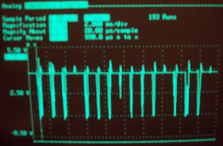

There appears to be a lot of noise in this image due to aliasing with the carrier. Below is a zoom in on the pulses. The smaller pulse has a pulse width of about 1.4ms and the longer pulse has a width of 2.4ms. Looking at the vishay datasheet:
I have usually use the sony protocol which uses a different set of pulse widths. (1.2 ms for 0 and 1.8 ms for 1.) Take a look at this page for an explanation:
PS:
Here is a nice overview of how IR remotes work:
http://www.sbprojects.com/knowledge/ir/ir.htm
Ok, I think I found what the pololu beacon is using. It appears that the pololu beacon is using what looks like the RCA protocol! Here is a link to the description:
http://www.sbprojects.com/knowledge/ir/rca.htm
I have a couple of universal remotes that will produce this protocol, so with any luck it should be pretty straightforward to drive the blimp with the IR remote! (A worthy project I think) This would require no additional hardware or weight on the balloon.
http://www.sbprojects.com/knowledge/ir/ir.htm
Ok, I think I found what the pololu beacon is using. It appears that the pololu beacon is using what looks like the RCA protocol! Here is a link to the description:
http://www.sbprojects.com/knowledge/ir/rca.htm
I have a couple of universal remotes that will produce this protocol, so with any luck it should be pretty straightforward to drive the blimp with the IR remote! (A worthy project I think) This would require no additional hardware or weight on the balloon.
Thursday, January 15, 2009
Update
I tested the board with the 2 amp cord and motor works fine now. I was also able to plug in the transmitter to the board using some cables and got the thruster control to work; however, the battery died before I could adjust the aileron controls.
1.
2. right motor back
3. right motor forward
4. left motor back
5. left motor forward
6. IR right
7. IR back
8. IR front
9. IR left
10. Servos
11 LED S
12. LED N
13. LED W
14
15. Ultrasonic out
16. Ultrasonic in
17. LED E
This is a list of pins and the things that they control. The numbers on the IR receiver are 19 711 v34156.
Alright, now for some fun stuff.
I was able to program the LED's to blink:
and here is a video of the ultrasound and motor combination. Note: the code for the ultrasound is a redone version of the original code, i just played with the names and things like that. I was not able to get it to do analog read....yet
Still working on the IR system at the moment...
1.
2. right motor back
3. right motor forward
4. left motor back
5. left motor forward
6. IR right
7. IR back
8. IR front
9. IR left
10. Servos
11 LED S
12. LED N
13. LED W
14
15. Ultrasonic out
16. Ultrasonic in
17. LED E
This is a list of pins and the things that they control. The numbers on the IR receiver are 19 711 v34156.
Alright, now for some fun stuff.
I was able to program the LED's to blink:
and here is a video of the ultrasound and motor combination. Note: the code for the ultrasound is a redone version of the original code, i just played with the names and things like that. I was not able to get it to do analog read....yet
Still working on the IR system at the moment...
Wednesday, January 14, 2009
Multiple Beacons
When you have finished everything in the previous post, take a look at this.
http://diydrones.com/profiles/blogs/705844:BlogPost:39610
It looks like they haven't solved this problem either. If you can read the part numbers off the IR receivers, I can do a bit of research. I am afraid that they used 56 Khz units on the board.
http://diydrones.com/profiles/blogs/705844:BlogPost:39610
It looks like they haven't solved this problem either. If you can read the part numbers off the IR receivers, I can do a bit of research. I am afraid that they used 56 Khz units on the board.
Subscribe to:
Posts (Atom)